5. CONFIGURE Menu
This chapter provides step-by-step instructions for the menu items under the CONFIGURE menu. Configuration options include:
-
Configuring serial ports
-
Configuring the local management consoles
-
Controlling interfaces and connections
-
Enrolling the OPERATIONS MANAGER to Lighthouse
- Creating and managing Playbooks
- Monitoring Power Distribution Units (PDUs)
-
Managing users, groups, and remote authentication
-
Configuring network resilience
-
Setting up services
-
Managing firewall settings
-
Setting date and time
-
Managing system settings
-
Configuring SNMP
5.1 Serial Ports
Click CONFIGURE > Serial Ports. A list of serial ports appears.
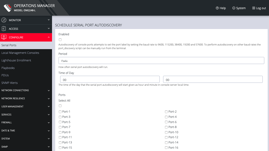
This page lets you select serial ports and Detect Selected ports.
You can Schedule Detection by clicking the button. This opens a page that allows you to select the ports and specify a time and period for port detection to occur.

Click the Edit Serial Port button under Actions next to the Serial Port you wish to configure. The Edit Serial Port page opens.
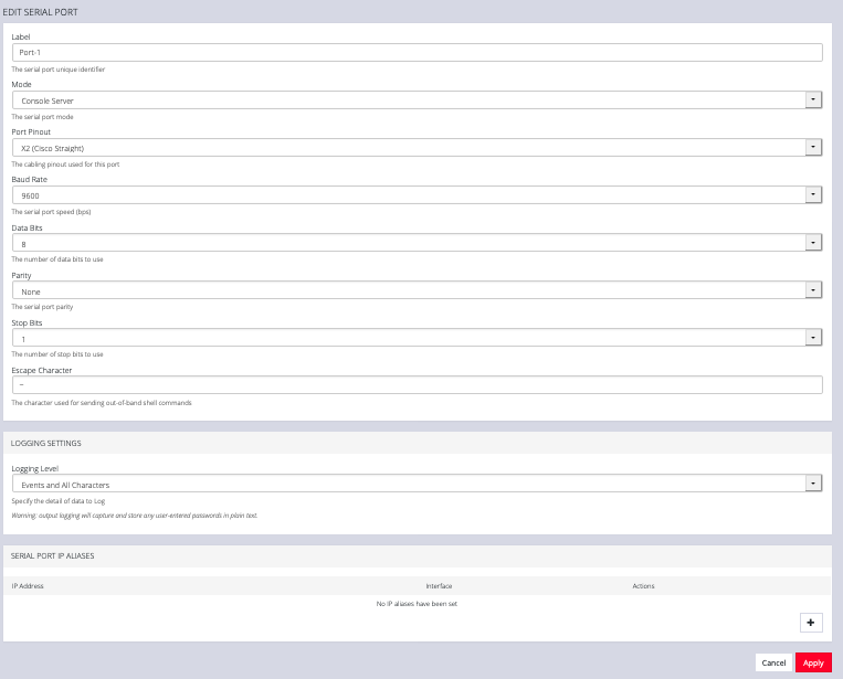
The Edit Serial Port page lets you configure the serial port’s:
-
Label: this can be used to locate this port using the Quick Search form on the ACCESS > Serial Ports page.
-
Mode: Disabled or Console Server
-
Pin out: X1 Cisco Rolled or X2 Cisco Straight
-
Baud Rate: 50 to 230,400 bps
-
Data Bits: 5, 6, 7, 8
-
Parity: None, Odd, Even, Mark, Space
-
Stop Bits: 1, 1.5, 2
-
Logging Levels
-
Serial Port Aliases
5.2 Local Management Consoles
You can edit settings or disable the local RJ45 serial console (Cisco straight -X2 pinout) and the USB serial console (needs user supplied micro-USB to USB-A cable).
To edit the settings of a local management console:
-
Click CONFIGURE > Local Management Consoles.
-
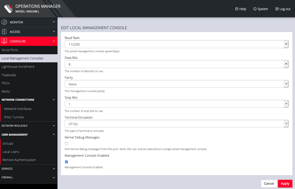
Click on the Edit Management Console Port button under Actions next to the console you wish to disable.
-
The Edit Local Management Console page lets you control:
-
Baud Rate
-
Data Bits
-
Parity
-
Stop Bits
-
Terminal Emulation
-
Enable or disable Kernel Debug Messages
-
Enable or disable the selected Management Console
-
NOTE: Enabling Kernel Debug Messages can only be applied to a single serial management console.
To disable a local management console, click CONFIGURE > Local Management Consoles. Click on the Disable Management Console Port button under Actions next to the console you wish to disable.
5.3 Interfaces and Connections
For instructions on adding, editing, or deleting network connections, see 2.8 Changing the IP Address of the Primary LAN Port.
5.4 Lighthouse Enrollment
Opengear appliances can be enrolled into a Lighthouse instance, providing centralized access to console ports, NetOps Automation, and central configuration of Opengear devices.
To enroll your OPERATIONS MANAGER to a Lighthouse instance, you must have Lighthouse installed and have an enrollment token set in Lighthouse.
To set an enrollment token in Lighthouse, click on CONFIGURE > LIGHTHOUSE ENROLLMENT > Enrollment Settings page, and enter an Enrollment Token.

To enroll your OPERATIONS MANAGER in this Lighthouse instance:
-
Click CONFIGURE > Lighthouse Enrollment.

-
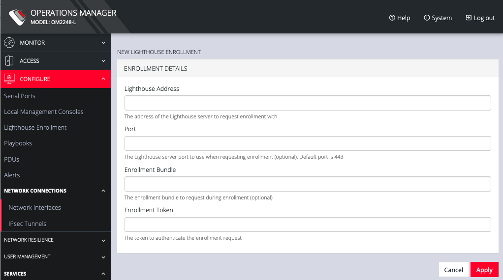
Click on the Add Lighthouse Enrollment button on the bottom right. The New Lighthouse Enrollment page opens.
-
Enter the IP address or fully qualified domain name of the Lighthouse instance and the Enrollment Token you created in Lighthouse. Optionally enter a Port and an Enrollment Bundle (see the Lighthouse User Guide for more information).
-
Click Apply.
NOTE: Enrollment can also be done directly via Lighthouse using the Add Node function. See the Lighthouse User Guide for more instructions on enrolling Opengear devices into Lighthouse.
5.5 Playbooks
Playbooks are configurable systems that periodically check if a Trigger condition has been met. They can be configured to perform a one or more specified Reaction. To create a new Playbook, select Configure > Playbooks.

Click the Plus button to create a new Playbook.
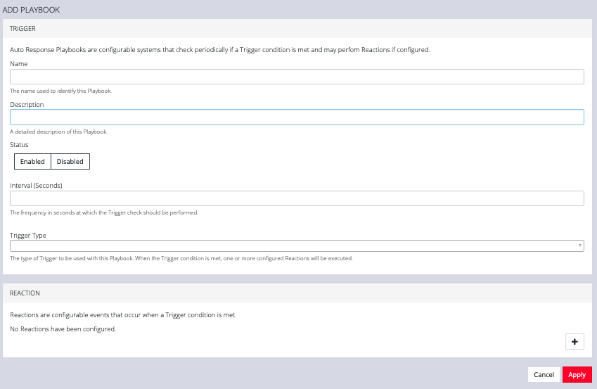
- Enter a Name for the Playbook.
- Add a Description.
- Select Enabled to activate the Playbook after you have created it.
- Enter an Interval in seconds to control the frequency that the Trigger will be checked.
- Choose the type of Trigger to use from the Trigger Type drop down.
- In the Reaction section, click the Plus and click on specific Reactions for this Playbook.
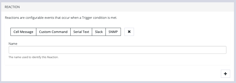
Clicking on each Reaction opens a custom screen to provide necessary information. When you are finished, click Apply.
After you have created Playbooks, you can Edit orDelete them from the Configure > Playbooks page.
To monitor current Playbooks, click on Monitor > Playbooks. Choose the time period if desired,and filter by Name of Playlist to view any that have been triggered.
5.6 PDUs
One or more Power Distribution Units (PDUs) , both Local and Remote can be monitored. To add information for a PDU, select Configure > PDUs.

Click the Plus button to configure a new PDU.
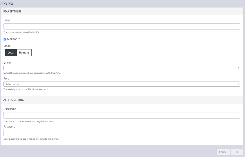
- Enter a Label for this PDU.
- Select the Monitor checkbox.
- Choose Local or Remote.
- Select the appropriate Driver from the drop-down list.
- Select the Port.
- Add a Description.
- Under Access Settings, enter a Username and Password to use when connecting to the device.
- When you are finished, click Apply.
After you have created PDUs, you can Edit orDelete them from the Configure > PDUs page.
5.7 Alerts
On the Configure > Alerts page, you can add and delete SNMP alerts.
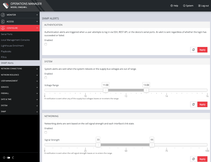
You can set triggers to send SNMP alerts for the following:
-
Authentication: when a user attempts to log in via SSH, REST API, or the device's serial ports. An alert is sent regardless of whether the login has succeeded or failed.
-
System: when the system reboots or the supply bus voltages are out of range. Use the slider to adjust the upper and lower voltage range.
-
Networking: based on the cell signal strength and each interface's link state.Use the slider to adjust the upper and lower signal strength.
-
Configuration: when changes occur to the system configuration.
NOTE: Manage the SNMP settings for these alerts on the CONFIGURE > SNMP > SNMP Alerts Protocol Configuration page.
5.8 Network Connections
The Network Connections menu contains the Network Interfaces and IPsec Tunnels settings.
For Network Interface configuration, see Chapter 2.5 for details.
On the CONFIGURE > NETWORK CONNECTIONS > IPsec Tunnels page, you can create, edit, and delete IPsec tunnels.

To create an IPsec tunnel:
-
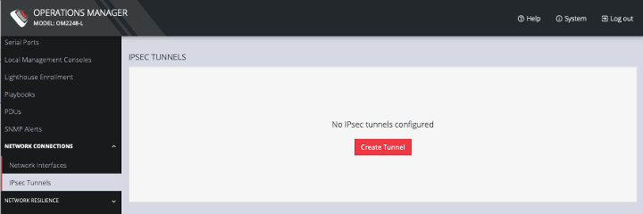
Click CONFIGURE > NETWORK CONNECTIONS > IPsec Tunnels.
-
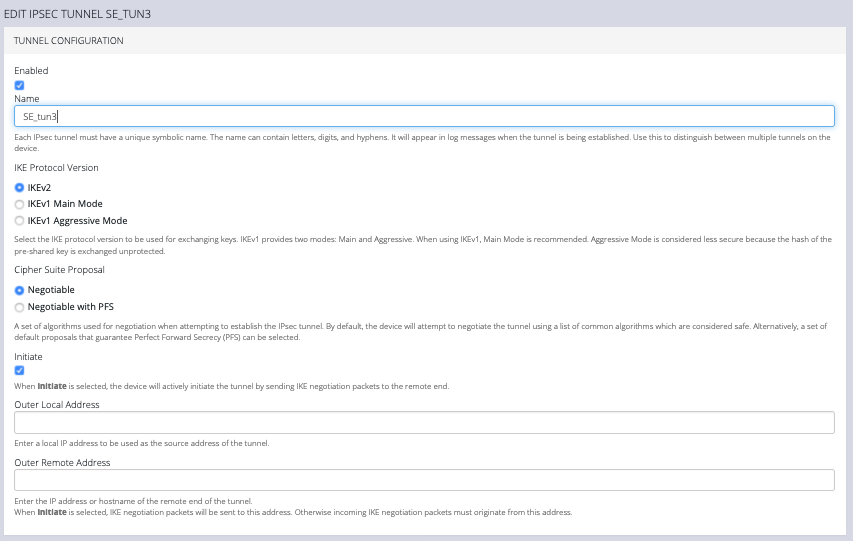
Click CREATE TUNNEL. This opens the EDIT IPSEC TUNNEL page.
-
In the top section of the page, TUNNEL CONFIGURATION, click the Enabled check box and give your new tunnel a name.
-
Select an IKE Protocol Version to use for exchanging keys. IKEv1 provides two modes: Main and Aggressive. When using IKEv1, Main Mode is recommended. Aggressive Mode is considered less secure because the hash of the pre-shared key is exchanged unprotected.
-
Select a Cipher Suite Proposal. This is a set of algorithms used for negotiation when attempting to establish the IPsec tunnel. By default, the device will attempt to negotiate the tunnel using a list of common algorithms which are considered safe. Alternatively, a set of default proposals that guarantee Perfect Forward Secrecy (PFS) can be selected.
-
Click the Initiate checkbox to actively initiate the tunnel by sending IKE negotiation packets to the remote end.
-
Enter an Outer Local Address, a local IP address to use as the source address of the tunnel
-
Enter an Outer Remote Address, the IP address or hostname of the remote end of the tunnel.
-
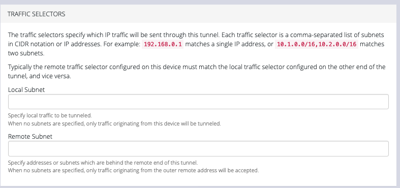
Scroll down to the Traffic Selectors section of the page.
-
Enter a Local Subnet and Remote Subnet.
-
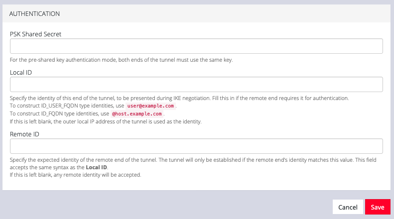
Scroll down to the third section, AUTHENTICATION.
-
Enter a PSK Shared Secret.
-
Enter a Local ID and Remote ID.
-
Click Save. The new tunnel is now listed on the CONFIGURE > NETWORK CONNECTIONS > IPsec Tunnels page.
5.9 Network Resilience
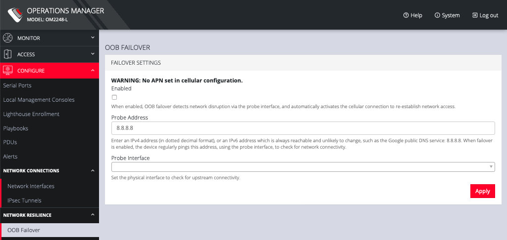
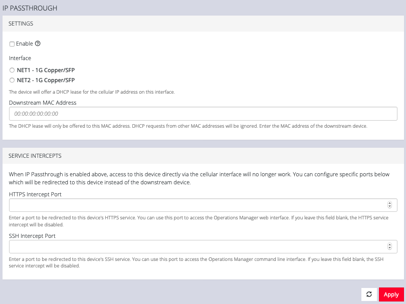
Under the NETWORK RESILIENCE menu, you can manage OOB failover and IP Passthrough settings.
5.9.1 OOB failover
To manage Out of Band failover:
5.9.2 IP Passthrough
To manage IP Passthrough settings:
5.10 User Management
Under the User Management menu, you can create, edit, and delete groups and users, as well as assign users to groups. You can also set up remote user authentication.
5.10.1 Groups
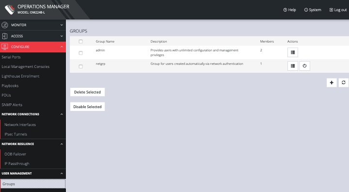
To create a new group:
-
Select CONFIGURE > User Management > Groups.
-
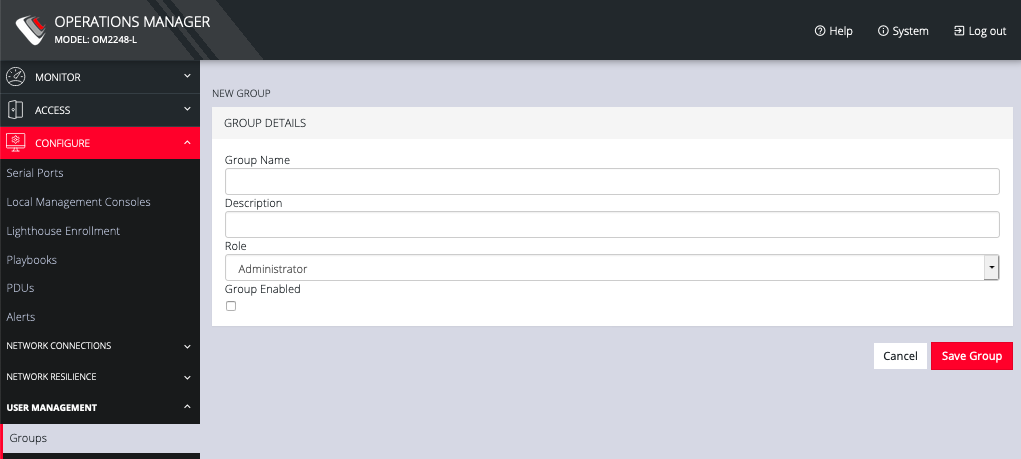
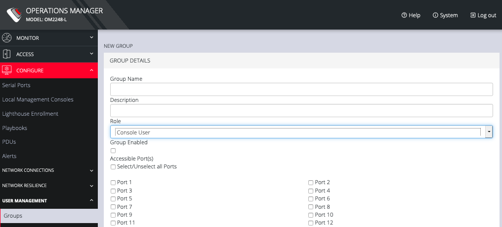
Click the Plus button. The New Group page opens.
-
Enter a Group Name, Description, and select a Role for the group.
-
Choosing the Console User role allows you to select specific ports this group will be able to access.
-
Click the Group Enabled checkbox to enable the group. After creation, groups can also be enabled or disabled from the CONFIGURE > User Management > Groups page.
-
Click Save Group.
NOTE: Group Name is case sensitive. It can contain numbers and some alphanumeric characters. When using remote authentication, characters from a user's remote groups that are not allowed are converted to underscores during authentication. Local groups can be created that take that into account, allowing the authentication to continue.
If the Role selected is Administrator, members of the group have access to all nodes.
To modify an existing group:
-
Select CONFIGURE > User Management > Groups.
-
Click Edit in the Actions section of the group to be modified and make desired changes.
-
Click Save Group.
The CONFIGURE > User Management > Groups page also allows administrators to delete a group. Users who were members of the deleted group lose any access and administrative rights inherited from the group.
NOTE: The netgrp group is inherited as the primary group for all remote AAA users who are not defined locally. By default, netgrp has the Administrator role and is disabled. It must be enabled to take effect for remote AAA users.
5.10.2 Local Users
To create a new user:
-
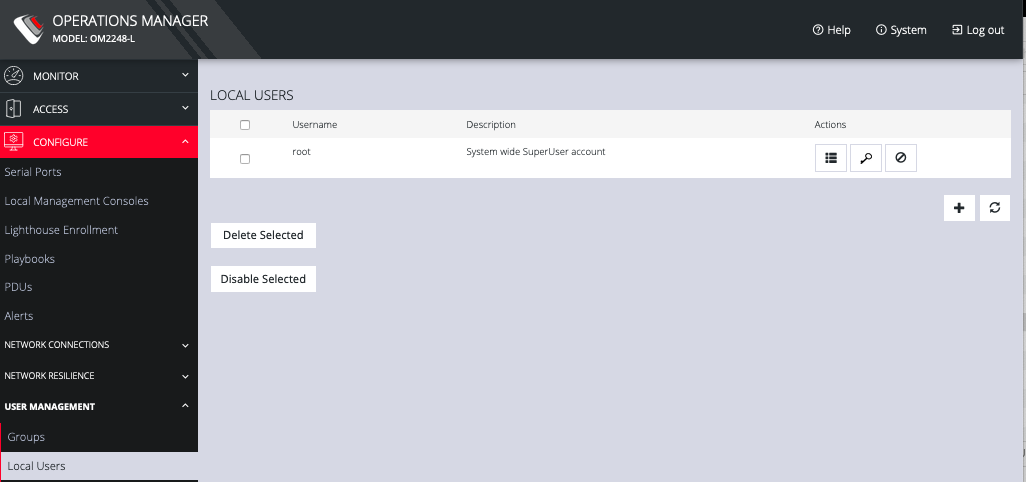
CONFIGURE > User Management > Local Users.
-
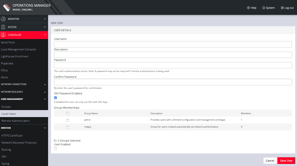
Click the + button. The New User dialog appears.
-
Enter a Username, Description, and Password.
-
Re-enter the Password in the Confirm Password field.
-
Select the Enabled checkbox.
-
Click Apply.
To create a new user without password which causes them to fall back to remote authentication:
-
Select CONFIGURE > User Management > Remote Authentication
-
Select a Scheme.
-
Enter Settings and click Apply.
-
Select CONFIGURE > User management > Local Users
-
Click the + button. The New User dialog loads.
-
Enter a Username, Description.
-
Select the Remote Password Only checkbox.
-
Select the Enabled checkbox.
-
Click Apply.
To modify an existing user:
-
Select CONFIGURE > User management > Local Users
-
Click the Edit User button in the Actions section next to the user to be modified and make desired changes.
-
Click Save User.
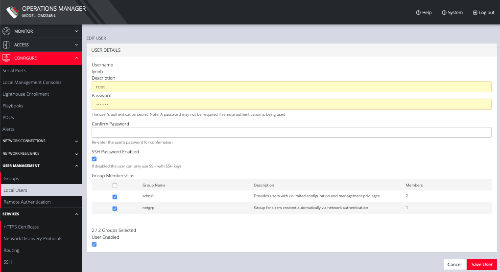
The Edit Users dialog allows the user’s Description to be changed, Group Memberships modified, and the user’s Password to be reset. The username cannot be changed. To disable a user, uncheck the Enabled checkbox.
Disabled users cannot login to the OPERATIONS MANAGER using either the Web-based interface or via shell-based logins.
To manage SSH authorized keys for a user:
-
Select CONFIGURE > User management > Local Users
-
Click the Manage SSH Authorized Keys button in the Actions section next to the user.

-
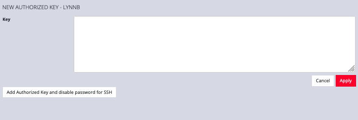
Click the Plus button to add a new key. This opens the NEW AUTHORIZED KEY page for this user.
-
Enter the key and click Apply. You can also click on Add Authorized Key and disable password for SSH for this user from this page.
-
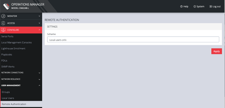
To delete a key, click CONFIGURE > USER MANAGEMENT > Local Users and click the Authorized Key button for the user.
-
Click the Delete button next to the key you wish to remove.
To delete a user:
-
Select CONFIGURE > User management > Local Users
-
Click the Delete User button in the Actions section next to the user to be deleted.
-
Click Yes in the Confirmation dialog.
5.10.3 Remote Authentication
The OPERATIONS MANAGER supports three AAA systems:
-
LDAP (Active Directory and OpenLDAP)
-
RADIUS
-
TACACS+
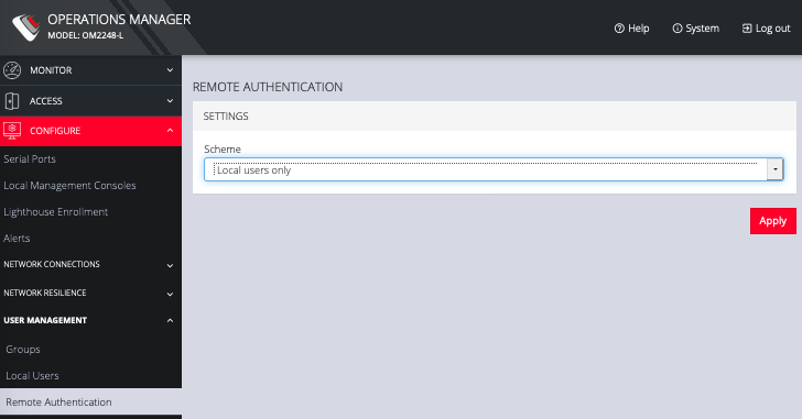
To begin, select CONFIGURE > User Management > Remote Authentication.
To configure LDAP authentication:
-
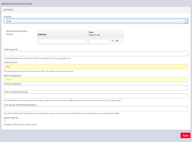
Under CONFIGURE > User Management > Remote Authentication, select LDAP from the Scheme drop-down menu.
-
Add the Address and optionally the Port of the LDAP server to query.
-
Add the Base DN that corresponds to the LDAP system being queried.
For example, if a user’s distinguished name is cn=John Doe,dc=Users,dc=ACME,dc=com, the Base DN is dc=ACME,dc=com
-
Add the Bind DN. This is the distinguished name of a user with privileges on the LDAP system to perform the lookups required for retrieving the username of the users, and a list of the groups they are members of.
-
Add the password for the binding user.
-
Add the Username Attribute. This depends on the underlying LDAP system. Use sAMAccountName for Active Directory systems, and uid for OpenLDAP based systems.
-
Add the Group Membership Attribute. This is only needed for Active Directory and is generally memberOf.
-
If desired, check Ignore referrals option. When checked, LDAP will not follow referrals to other remote authentication servers when logging users in. If multiple remote authentication servers exist on the network, checking this option may improve login times.
NOTE: Multiple servers can be added. The LDAP subsystem queries them in a round-robin fashion.
To configure RADIUS:
-
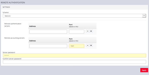
Under CONFIGURE > User Management > Remote Authentication, select RADIUS from the Scheme drop-down menu.
-
Add the Address and optionally the Port of the RADIUS authentication server to query.
-
Add the Address and optionally the Port of the RADIUS accounting server to send accounting information to.
-
Add and confirm the Server password, also known as the RADIUS Secret.
NOTE: Multiple servers can be added. The RADIUS subsystem queries them in a round-robin fashion.
To provide group membership, RADIUS needs to be configured to provide a list of group names via the Framed-Filter-Id attribute. The following configuration snippet shows how this can be configured for FreeRADIUS:
operator1 Auth-Type := System
Framed-Filter-ID = ":group_name=west_coast_admin,east_coast_user:"
NOTE: The Framed-Filter-ID attribute must be delimited by the colon character.
To configure TACACS+:
-
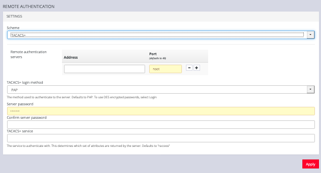
Under CONFIGURE > User Management > Remote Authentication, select TACACS+ from the Scheme drop-down menu.
-
Add the Address and optionally the Port of the TACACS+ authentication server to query.
-
Select the Login Method. PAP is the default method. However, if the server uses DES-encrypted passwords, select Login.
-
Add and confirm the Server password, also known as the TACACS+ Secret.
-
Add the Service. This determines the set of attributes sent back by the TACACS+ server
NOTE: Multiple servers can be added. The TACACS+ subsystem queries them in a round-robin fashion.
To provide group membership, TACACS+ needs to be configured to provide a list of group names This following configuration snippet shows how this can be configured for a tac_plus server:
user = operator1 {
service = raccess {
groupname = west_coast_admin,east_cost_user
}
}
To do this with Cisco ACS, see Setting up permissions with Cisco ACS 5 and TACACS+ on the Opengear Help Desk.
5.11 Services
The CONFIGURE > Services menu lets you manage services that work with the OPERATIONS MANAGER.
5.11.1 HTTPS Certificate
The OPERATIONS MANAGER ships with a private SSL Certificate that encrypts communications between it and the browser.
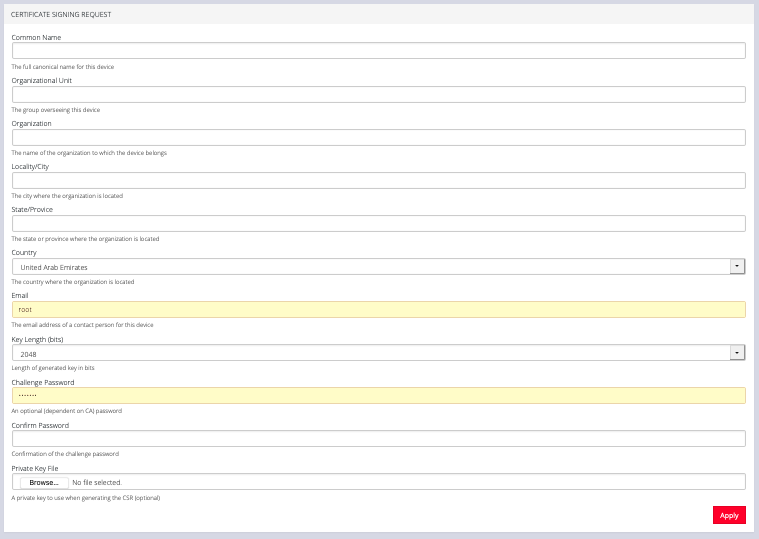
To examine this certificate or generate a new Certificate Signing Request, select CONFIGURE > Services > HTTPS Certificate. The details of the Current SSL Certificate appear.
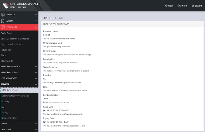
Below this listing is a Certificate Signing Request form, which can be used to generate a new SSL certificate.
5.11.2 Network Discovery Protocols
The OPERATIONS MANAGER displays LLDP/CDP Neighbors when enabled for a connection. See CONFIGURE > SERVICES > Network Discovery Protocols to enable/disable.
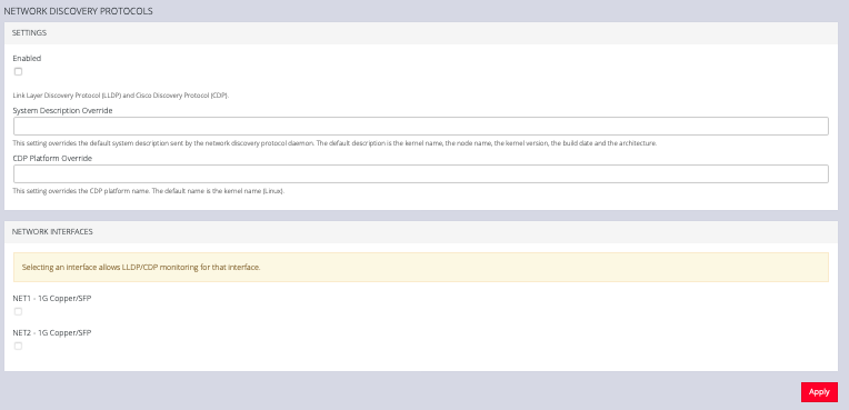
The CONFIGURE > SERVICES > Network Discovery Protocols > LLDP/CDP NEIGHBORS page allows you to enable this service by clicking the Enable checkbox. You can set a System Description that overrides the default system description sent by the network discovery protocol daemon. The default description is the kernel name, the node name, the kernel version, the build date and the architecture. You can also enter a value in the CDP Platform Override to override the CDP platform name. The default name is the kernel name (Linux). Select one or more checkboxes in the NETWORK INTERFACES section of the page and click Apply.
5.11.3 Routing
You can enable routing protocols on this page. Select CONFIGURE > SERVICES > Network Discovery Protocols > Routing.
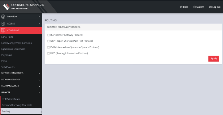
Select any of the following and click the Apply button:
-
BGP (Border Gateway Protocol)
-
OSPF (Open Shortest Path First Protocol)
-
IS-IS (Intermediate System to System Protocol)
-
RIPD (Routing Information Protocol)
5.11.4 SSH
To modify the port used for connecting to serial consoles via SSH, click CONFIGURE > SERVICES > SSH.
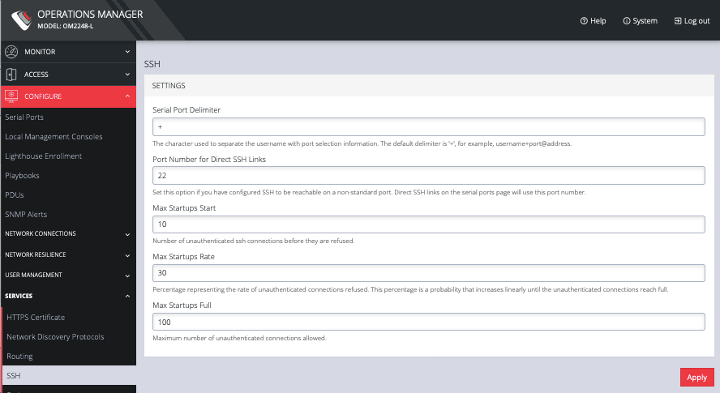
This page also lets you set the delimiting character used to separate the username with port selection information. The default delimiter is a plus sign (+). For example, username+port@address.
You can change more values on this page.
-
Max Startups Start, the number of unauthenticated connections before they are refused.
-
Max Startups Rate is a percentage that represents the rate of unauthenticated connections refused. This percentage is a probability that increases linearly until the unauthenticated connections reach full.
-
Max Startups Full is the number of unauthenticated connections allowed.
5.11.5 Syslog
Administrative users can specify multiple external servers to export the syslog to via TCP or UDP.
Select CONFIGURE > Services > Syslog.
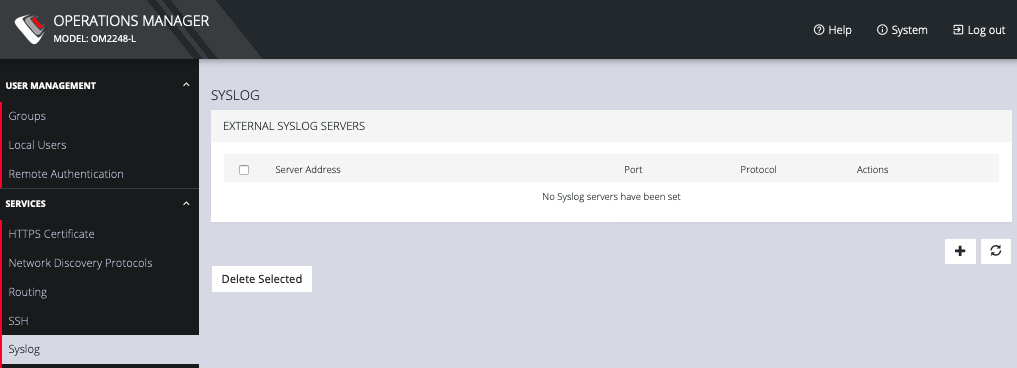
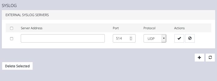
This page lists any previously added external syslog servers. To add a new one,
-
Click the Plus button. The External Syslog Servers form appears.
-
Enter the Server Address.
-
Enter the Protocol, either UDP or TCP.
-
Enter the correct Port. If no port is entered, UDP defaults to port 514 and TCP defaults to 601.
-
Click Apply.
To edit an existing syslog server, click the Edit button under Actions. Delete a server by clicking the Delete button or the checkbox next to multiple servers and the Delete Selected button.
5.11.6 Session Settings
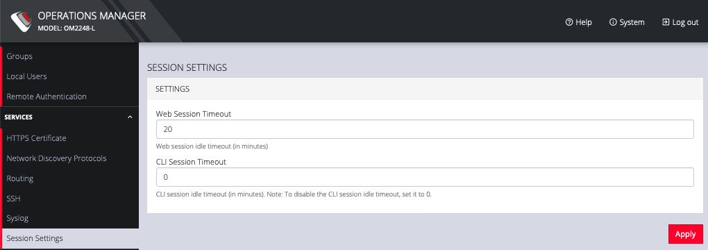
To modify Web and CLI session settings select SETTINGS > Services > Session Settings.
-
Web Session Timeout: This value can be set from 1 to 1440 minutes.
-
CLI Session Timeout: This value can be set from 1 to 1440 minutes or set it to 0 to disable the timeout. Changes take effect the next time a user logs in via the CLI.
5.12 Firewall
The CONFIGURE > FIREWALL menu lets you change firewall management, rules, zones, and services.
To change firewall management settings click CONFIGURE > FIREWALL > Management.
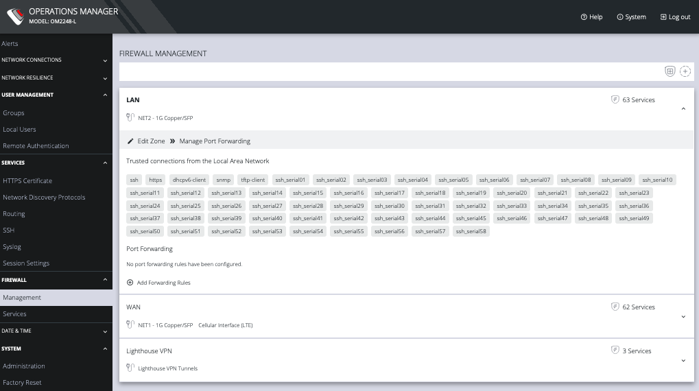
You can expand each zone by clicking the Expand arrow on the right. Once expanded, you can click Edit Zone to change settings for a particular zone.
The EDIT FIREWALL SETTINGS page allows you to:
-
Modify the Name of the zone
-
Add a Description for this zone
-
Permit all Traffic
-
Masquerade Traffic
-
Select Physical Interfaces
-
Manage Permitted Services by clicking on Plus or Minus next to each
NOTE: You can use the Filter Interfaces and Filter Available Services text boxes to navigate through the lists.
The FIREWALL MANAGEMENT page also contains quick links to Add Firewall Service (shield icon on upper right), Add Firewall Zone (plus icon on upper right), and Edit Zones pages (pencil icon in expanded view) for the currently selected zone.
Additional menu options under CONFIGURE > FIREWALL are Rules, Services, and Zones.
Manage Firewall Rules
Click CONFIGURE > FIREWALL > Services. This opens the SERVICES page with a list of all firewall rules.
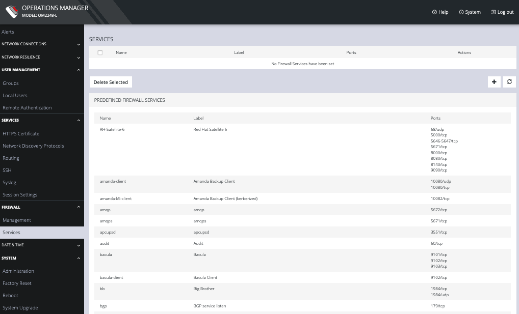
Services can be added, deleted, or edited from this page. Scroll to the bottom of the page to access the Plus button to add a new service.

Enter a Service description and a Zone for the new rule.
Manage Firewall Zones
Click CONFIGURE > FIREWALL > MANAGEMENT.
This opens the ZONES page with a list of all firewall zones.
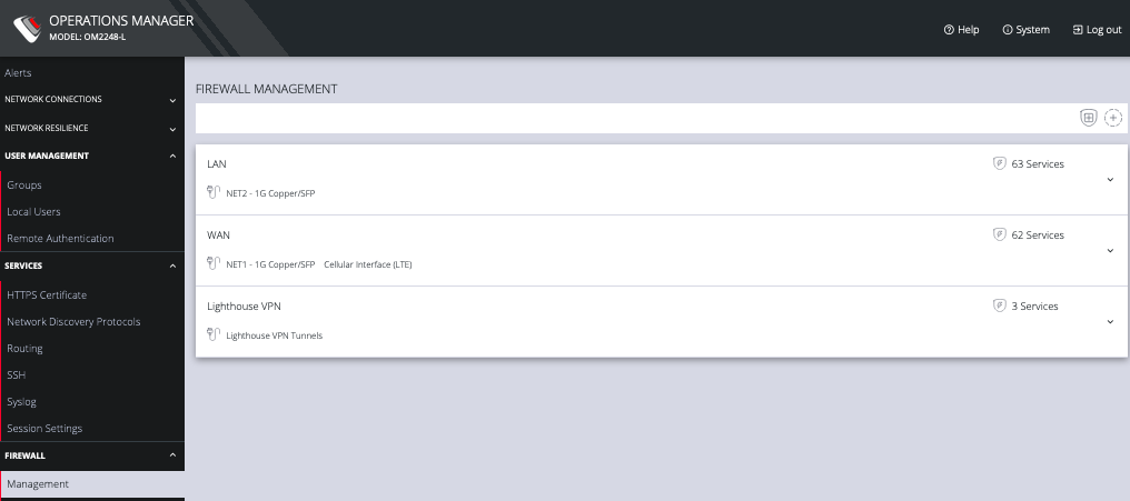
Zones can be added, deleted, or edited from this page. Click the PLUS symbol on the top right of the page to add a new zone.
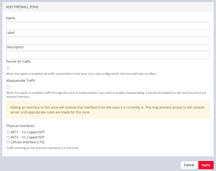
The ADD FIREWALL ZONE page allows you to:
-
Modify the Name of the zone
-
Add a Label for the zone
-
Add a Description for this zone
-
Permit all Traffic
-
Masquerade Traffic
-
Select Physical Interfaces
Manage Firewall Services
Click CONFIGURE > FIREWALL > Services. This opens the SERVICES page with a long list of predefined firewall services.
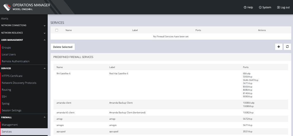
Services can be added, deleted, or edited from this page.
NOTE: Predefined services cannot be edited.
Click the Plus button to add a new service.

Enter a Name, Label, Port #, and Protocol. Select a Protocol (TCP or UDP) from the Plus button menu. Add more Ports and Protocols as desired and click Apply.
5.13 Date & Time
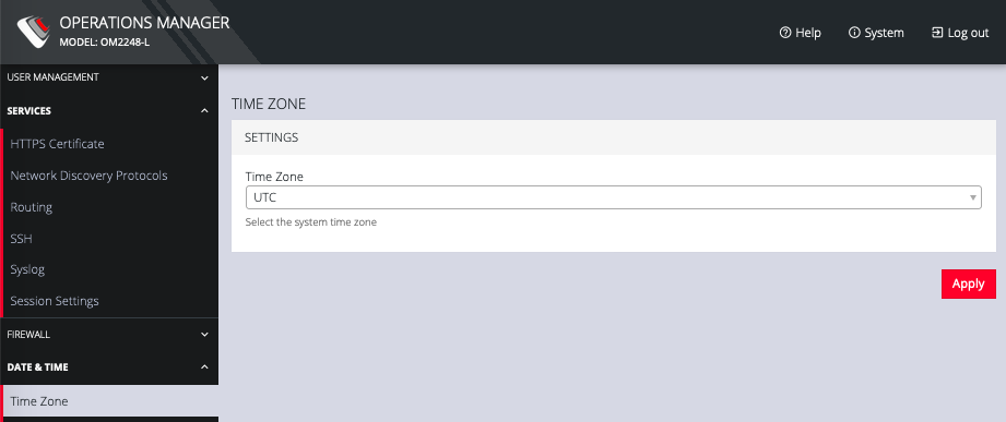
To set the time zone:
-
Click CONFIGURE > Date & Time > Time Zone.
-
Select the OPERATIONS MANAGER’s time-zone from the Time Zone drop-down list.
-
Click Apply.
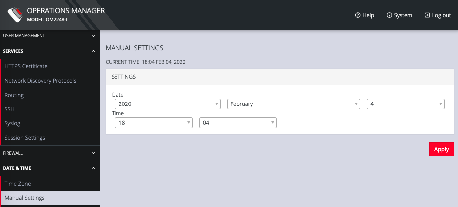
To set the correct time and date, either
-
Click CONFIGURE > Date & Time > Manual Settings.
-
Enter the current Date and Time.
-
Click Apply.
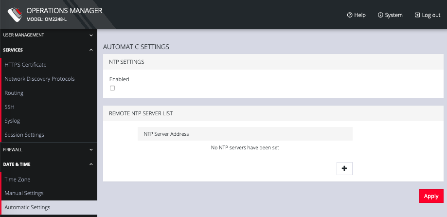
or
-
Click CONFIGURE > Date & Time > Automatic Settings.
-
Click the Enabled checkbox.
-
Enter a working NTP Server address in the NTP Server Address field.
-
Click Apply.
5.14 System
The CONFIGURE > System menu lets you change the OPERATIONS MANAGER’s hostname, perform system upgrades, and reset the system.
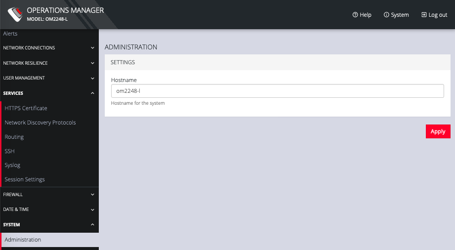
To set the hostname for the OPERATIONS MANAGER:
-
Click CONFIGURE > System > Administration.
-
Edit the Hostname field.
-
Click Apply.
You can perform a factory reset, where logs and docker containers are preserved and everything else is reset to the factory default.
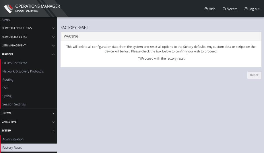
To return the OPERATIONS MANAGER to its factory settings:
-
Select CONFIGURE > System > Factory Reset.
-
Select the Proceed with the factory reset checkbox.
-
Click Reset.
NOTE: This performs the same operation as the hard factory erase button covered section 1.7. This resets the appliance to its factory default settings. Any modified configuration information is erased. You will be prompted to log in and must enter the default administration username and administration password (Username: root Password: default). You will be required to change this password during the first log in.
To reboot the OPERATIONS MANAGER:
Select CONFIGURE > System > Reboot.
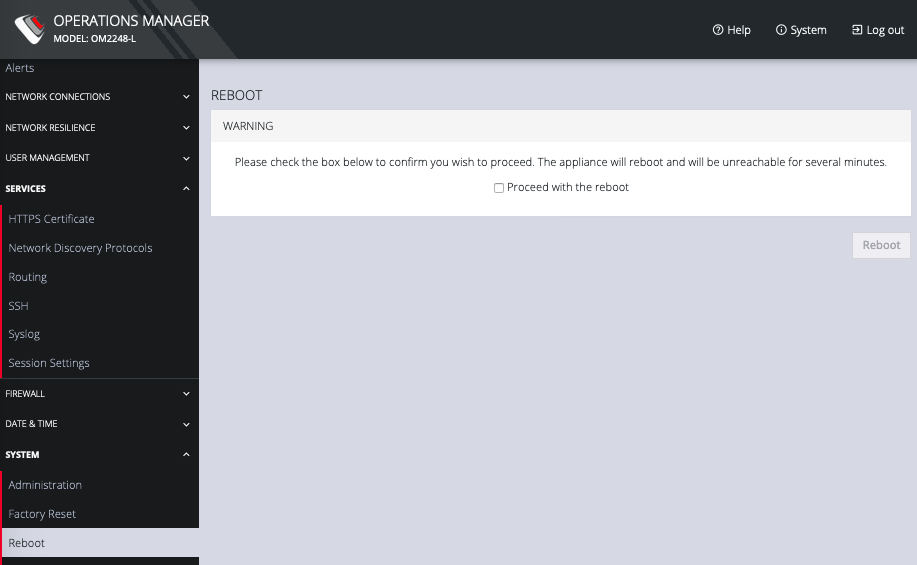
SelectProceed with the reboot and click Reboot.
You can perform a system upgrade when new firmware is released. After specifying the location of the firmware and beginning the process, the system will unavailable for several minutes and then reboot. Unlike a factory reset, users, and other configuration data is maintained.
To perform a system upgrade:
-
Select CONFIGURE > System > System Upgrade.
-
Select the Upgrade Method, either Fetch image from HTTP/HTTPS Server or Upload Image.
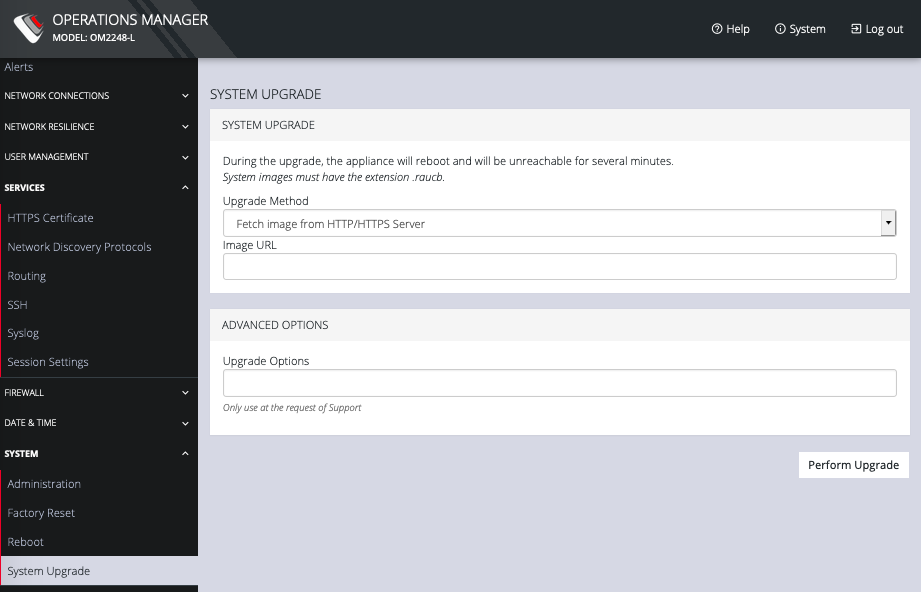
If upgrading via Fetch image from HTTP/HTTPS Server:
-
Enter the URL for the system image in the Image URL text-entry field.
-
Click Perform Upgrade.
Or if upgrading via Upload Image:
-
Click the Choose file button.
-
Navigate to the directory containing the file.
-
Select the file and press Return.
-
Click Perform Upgrade.
NOTE: The Advanced Options section should only be used if a system upgrade is being performed as part of an Opengear Support call.
Once the upgrade has started, the System Upgrade page displays feedback as to the state of the process.